CARF Toolkit
Examples
Plan documentation:
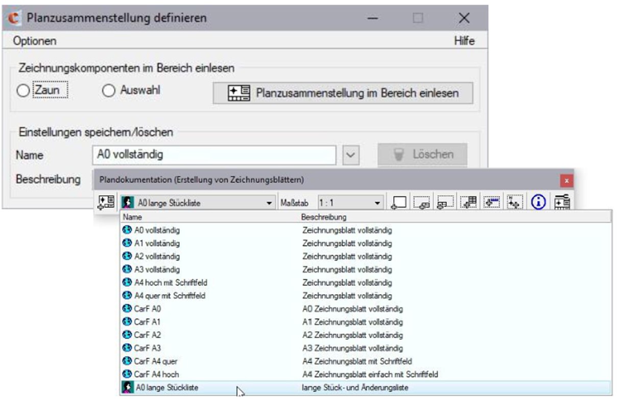
The plan documentation toolbox is used to create drawing sheets consisting of frames, title blocks, change index fields, parts lists, scale bars and north arrow cells. All drawing sheet components can be placed individually or in predefined plan compilations. The data is defined in XML files and cell libraries.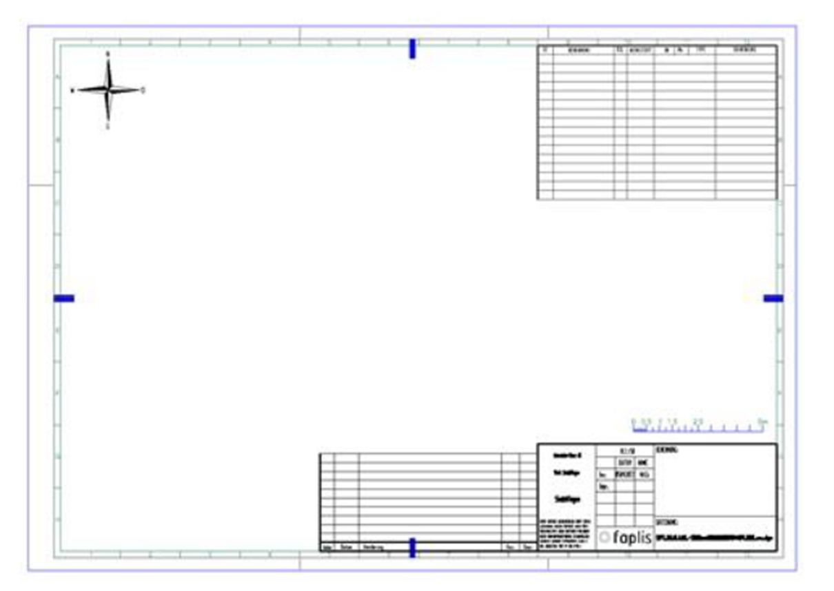
Compare references:
The elements of two references (master and comparison reference) can be compared with each other. The current references of the drawing are available for selection in the two combo boxes. The icons represent the respective reference. All other geometries are switched off until the next screen is built-up.Reassign levels:
Meaning of the background colour
All elements that sit on levels which are not defined in DGN libraries are displayed with a background colour. The programme assumes that all permissible target levels (new levels) are defined in DGN Libraries. These can be assigned to the active drawing using the MicroStation system variable MS_DGNLIBLIST. All old levels that do not need to be changed, i.e. that are identical with defined DGN library levels, are displayed in the list box without a background colour.
Individual change of levels, colour, line values
New levels can now be assigned to the old levels. The list box contains a corresponding selection editor in each cell for this purpose.
Calculate element size:
The selected drawing area is read in, and the internal memory size of all selected elements is determined. This data size is then displayed in bytes, kilobytes (KB) and megabytes (MB). The status bar contains an additional display in words, the internal MicroStation format, which is also displayed by the MicroStation element info function. 1 word = 2 byte.Area selection:
- All elements of the loaded drawing and reference models are captured
- Only elements of the active model are included
- Capture all visible elements in the fence
- Capture all visible elements of the active selection
The design file is saved in a compressed format so that the memory required on the hard disk is significantly less than the internal memory (RAM) required to load the drawing elements.

Features of the CARF Toolkit
- Mark CARF elements and external elements
- Analysis of DGN drawings
- Calculation of the memory usage of DGN drawing elements
- CARF Info, display standard linkage of cells
- Display and conversion of pseudo cells
- Reassign levels
- Compare DGN drawings
- Compare references
- Search for DGN drawing elements by ID
- Set view windows
- Plan documentation, creation of drawing sheets
- Simplify complex cell geometry
- Project 3d geometry into the XY plane